I am working on the PCB layout for a hardware design and production prototype for a dramatically more capable A.C.E. or MMI detector system. It will include a GPS clock, which can be used to produce samples from physically-separated systems synchronized to about +/-20ns. This allows testing of many new phenomena, such as mentally induced entanglement, and other correlated signals that move faster than light (the speed of thought). The system includes three orthogonal sensors that can indicate the direction from which a disturbance or influence originates.
Hopefully this will begin a new era of development and interest. Though this design and related firmware and software was/is extremely challenging, it is still just a first prototype. I will be happy to share more when real results are available.
2 Likes
Uhh this is amazing news. Sign me up to beta test whenever the time comes, I would also be glad to volunteer marketing this thing to potential testers/consumers
A brief update: I now have full PCB prototypes of the new system, which seems to be working electronically (just turned it on today). Next steps include implementation of a new algorithm that may increase signal to noise by a factor of 20-100 times when used in conjunction with the new hardware.
1 Like
Exciting times! Can’t wait to test / see the results.
I’m intrigued by the GPS clock sync, which sounds like an extremely high level of precision in timing across different locations, allowing experiments to be coordinated with near perfect accuracy, eliminating possible mistakes from timing differences in data collection.
The “three orthogonal sensors” are particularly interesting to me. Could you elaborate on how this approach either diverges from or builds upon the technologies and methodologies applied in the MED models?
Specifically, how might the precision synchronization and spatial detection capabilities of the system enhance our understanding or detection of MMI phenomena compared to the frameworks you’ve previously developed?
And are there any examples of practical applications of this new device, or is its purpose solely to test new phenomena?
I expect the GPS synchronization will allow timing at different locations to be matched within +/-50ns, or possibly better. That’s just 50 feet at the speed of light.
Previous MMI generators, including the Model MED100Kx8, did not give any consideration to directionality. Most of those generators used logic elements in FPGAs (Field-Programmable Gate Arrays) to construct the entropy harvesting circuits. If there is a directional component in those circuits, it would require detailed knowledge of the orientations of every transistor in each circuit, plus a high level of control of how they are interconnected.
Among other potential applications, knowing the precise time, location and directionality allows calculation of the direction of the influence or disturbance, and also if the “signal” has a measurable velocity. We may also test how groups of people in certain locations, or distributed widely cause a cumulative effect. Just a few examples – not a comprehensive list.
Yes, there are a number of practical applications, but I prefer to wait until I have tested some first.
So these sensors are similar to the electron tunneling devices, but with consideration for directionality?
I mean I am just guessing but that sounds like a step towards interstellar comms, and a million things that would probably benefit someone who played in the financial markets.
I am extremely interested in what these devices will tell us about the spatial characteristics of MMI phenomena, as finding hidden treasure was one of the original reasons I even thought MMI was interesting.
I’ll be anticipating these developments greatly
You have touched on some of my particular interests and reasons for developing this tech. I have always thought that any truly advanced race would have a way to communicate faster than light (FTL). Otherwise, they would remain totally isolated. Obviously this cannot be done using electromagnetic (radio) waves that cannot move FTL.
MMI dousing would be a form of real-time Randonauting, but with more specific targets and continuous feedback. A really long time ago I developed a 3D sensor for electromagnetic fields. I used it to look for mineral deposits, specifically gold and silver. I found that the conductivity of the ore deposits altered the ambient field – produced by power lines at 50 or 60Hz – in a very obvious way. I could easily find large buried ore by measuring and analyzing the electromagnetic field vectors in the space above the ore body.
This 3D plot, aligned geographically, shows an actual gold ore deposit associated with a large, buried quartz slab. I centered the plot so the large amplitude vector with shifted phase indicates the position of the ore. This is an example of what can be done with 3D field detection, and this was based on passively detecting ambient field variations (no active field generation used for this sensor).
2 Likes
Man this gave me goosebumps thinking about, its exactly the type of tech I was imagining was possible once I found out about PEAR and MMI. Super interested in reading more about what you’ve been dreaming up.
That’s a very exciting new approach! It will hopefully also provide more data to research whether there is a spatial directionality to MMI or not and to be able to rule out other forces that might influence the randomness. Looking forward to hearing more about test results.
For background, here is a picture of the electronics of the 3D Electromagnetic Field Sensor.
The data analysis for the plot above was done in February, 1998, so the design and hardware were completed some time before. You can see the type of prototype construction I used 26 years ago (mostly wire wrap) – amazingly crude compared to current designs.
There are three duplicate circuits, one for each dimension, which is a requirement to fully measure the 3D field vector. Much of the analog circuitry is the 60Hz bandpass filters required for sufficient signal-to-noise. I couldn’t find images of the detector coils (only film cameras in the “old days”). The detector was three solenoids taken from electromechanical relays, each mounted orthogonal to the others. A fourth solenoid was mounted at a nearby, stationary location aligned vertically and recorded simultaneously with the 3D sensor outputs to provide a reference phase. I used long cables to interconnect all the sensors, but a high-accuracy timer (such as a GPS clock) at the sensors would remove the need to physically interconnect each measurement point.
1 Like
To update: I tested the functionality of the first version on PCB, which all worked electronically. Through these tests, I was able to upgrade the design considerably. Although I have worked out a simple processing algorithm (for a start), I haven’t analyzed the signals yet, which will require some more software development.
The next version includes a general purpose I2C bus and connector through which a number of signals can be measured simultaneously. A large variety of physiological signals, such as EDR (electrodermal response, formerly GSR), PPG (photoplethysmograph), EMG (electromyograph), can be measured. Also, an alternate sensor for A.C.E. or other mentally-influenced measurement can be input this way.
These developments will make the new device, which I am now calling a 3D Quantum Field Detector, into a general purpose R/D development tool, with extensive capabilities. The precise timing allows the devices to be used locally or remotely (anywhere in the world), and individually or in a large array.
This is all very exciting. Thank you Scott.
One thing I was wondering; you talk about signal direction detection but how does that align with the idea of non-locality in MMI and the idea that mental influence can happen on a device despite distance (and presumably also direction)?
We don’t actually have any evidence concerning directionality of mental influence because we never had a way to measure before. However this detector is also intended to measure other, perhaps even cosmological sources, which could clearly have a direction. If there is no directionality, we would have a radio that receives every station at once, unless there is yet another way of tuning into a specific source…
Another thought is, if we have a good directional detector, we can begin to search for things that naturally produce “signals” that it can detect, or even artificial devices that can produce signals.
I am also excited to start finding out.
My mind is reeling at the possibilities. Keep us updated, Scott!
I filed a patent application yesterday for this new technology. I call the invention a 3D Quantum Field Detector. Here is the abstract:
The 3-Dimensional Quantum Field Detector (QFD3D) detects variations in the quantum field and determines the direction of these variations. The device includes three orthogonally oriented quantum detectors, each consisting of arrays of Zener diodes biased to produce shot noise. The detectors are aligned with geographic directions, with the Y axis pointing true north and the Z axis pointing vertically toward the zenith. Variations in the quantum field modulate the tunneling current through the detectors. Multiple measurements and signal processing increase the signal-to-noise ratio, providing the magnitude and direction of the detected signals.
Following is a list of potential applications:
The applications of the QFD3D device are vast and diverse, spanning multiple scientific, industrial and technological fields. Here are a few notable examples:
- Artificial Intelligence Integration : By integrating with AI algorithms, the QFD3D device can be used to analyze complex signal patterns for various applications. This includes enhancing machine learning models by providing additional quantum data inputs, improving the accuracy and capabilities of AI systems.
- Astronomical Observations : The QFD3D device can be used in astronomical observations to detect and analyze quantum disturbances from distant cosmic events. Its precise timing capabilities allow for synchronization of data from multiple devices located in different parts of the world, providing a comprehensive view of celestial phenomena.
- Communication Systems : The QFD3D device can be applied in developing advanced communication systems that leverage quantum field variations for transmitting and receiving information. This could lead to more secure and efficient communication methods.
- Environmental Monitoring : The device can be used to monitor environmental changes by detecting subtle quantum field variations that might correlate with specific environmental conditions or changes. This could be valuable in fields such as geology, meteorology, and oceanography.
- Medical Diagnostics : QFD3D devices can be integrated into advanced medical diagnostic tools to non-invasively detect and analyze quantum field disturbances that might correlate with physiological processes. This could lead to new diagnostic techniques and enhance the understanding of various medical conditions.
- Observation of Brain Activity Patterns : Information about neuronal activity can be decoded using AI algorithms to interpret the signals from one, or an array of QFD3D devices. The deivces are placed in proximity to the subject’s head; this placement should be consistent during training and use. Initially, a large database of signals is acquired for training the AI. The subject is asked to think a particular thought, which can include an image, sound, smell, feeling or taste. Each repetition of these thoughts, or visualizations, is synchronized with the data collection. The patterns the AI recognizes may be unique to each individual, though there will likely be some common patterns among subjects. Specific information, such as control commands, enables hands-free control of a wide variety of devices and applications.
- Scientific Experiments : The QFD3D device is ideal for scientific experiments that require precise measurement and analysis of quantum field disturbances. This includes experiments in quantum mechanics, such as observing entanglement or other quantum phenomena, where spacelike separation is crucial.
- Security and Surveillance : The device can be utilized in security and surveillance applications to detect unauthorized or suspicious activities through their quantum field signatures. This application can enhance the effectiveness of security systems by providing an additional layer of detection.
- Solar Observations : The QFD3D device can observe subtle changes in fusion or other quantum-based processes in the sun. This may allow earlier and more accurate prediction of solar storms and other event that can affect us, especially satellites and other high technology.
Here are a few figures from the application:
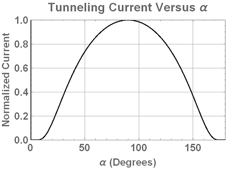
An example of tunneling current versus angle of incidence, Alpha. This is the basis for directional measurements.
3-dimenstional tunneling current sensor array
Block diagram of a preferred embodiment.
1 Like
I tried to upload more pictures, but it just pretends to do something, but never completes. Instead, here are links to Google drive.
Here is a link to a photo of the QFD3D PCB:
The plugin board at the right end is the GPS receiver board, connected to an active antenna (bottom). The upper connector on the right end is for supplemental data streams and peripheral devices, such as biological signals from EDR, PPG, EMG, EKG, EEG, etc., or physical measurements, such as ambient geomagnetic fields, solar activity, etc. The shield encloses the power supplies, the USB interface and the Propeller processing unit, to prevent interference with the low-noise section. The 3D sensors are mounted on the left end of the board, followed by ultra-low-noise amplification, low-pass antialiasing filter and the ADCs.
Here is a link to the drawings:
1 Like
This is awesome news Scott! Thank you.
Can you please explain how you were trying to upload the image and PDF and what error you got?
I tried myself and uploads seem to be working, so for reference purposes I’ll upload the two docs you refer to here:
QFD3D PCB:
And the Drawings PDF:
QFD3D_Drawings.pdf (197.1 KB)


